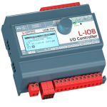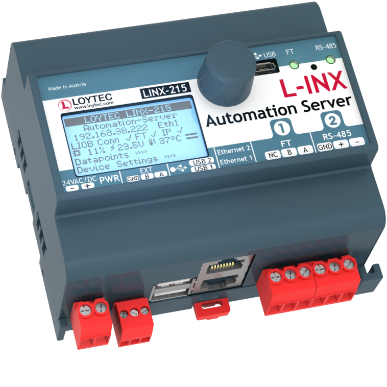
The L‑INX Automation Servers LINX‑215 are programmable automation stations with integrated graphical visualization for central automation tasks in BACnet and LonMark networks. They can integrate physical I/Os through L‑IOB I/O Modules via LIOB‑Connect, LIOB‑FT, or LIOB‑IP. Local operation and override is provided by the built-in jog dial and the backlit display (128×64 pixels). Device and data point information is shown on the display via symbols and in text format.
LonMark Systems can be integrated via IP‑852 (Ethernet/IP) or TP/FT‑10. In addition, the Automation Servers provides connectivity to concurrently integrate KNX, Modbus, and M‑Bus and connect as a gateway data points of different technological origin. The Automaton Servers feature an integrated IP‑852 router providing the complete feature set of corresponding L-IP devices.
BACnet can be integrated via BACnet/IP, BACnet/SC or BACnet MS/TP. In addition, the Automation Servers provide connectivity to concurrently integrate KNX, Modbus, and M‑Bus and connect as a gateway data points of different technological origin. Optionally, mathematical objects can be applied within a connection to calculate the data point output values depending on the formula used. The Automaton Servers feature a BACnet/SC router, BACnet/IP router including BBMD as well as Slave-Proxy functionality. LINX‑215 is BTL certified as B-BC (BACnet Building Controller).
The gateway functionality allows data communication between all communication technologies available on the device. Different technology data points are mapped through Local Connections on the device. The mapping of different technology data points on distributed devices is supported by Global Connections. L‑INX Automation Servers also support Smart Auto-Connect™ – the automatic generation of connections to substantially reduce engineering efforts and cost. All technology data points are automatically created as OPC XML‑DA and OPC UA data points.
Each L-INX Automation Server is equipped with two Ethernet ports. It can either be configured to use the internal switch to interconnect the two ports or every port is configured to work in a separate IP network.
When the Ethernet ports are configured for two separate IP networks, one port can be connected for instance to a WAN (Wide Area Network) with enabled network security (HTTPS) while the second port can be configure to be connected to an insecure network (LAN) where the standard building automation protocols like BACnet/IP, LON/IP, or Modbus TCP are present. These devices also feature firewall functionality of course to isolate particular protocols or services between the ports. The built-in VPN function provides for simple VPN setup and secure access to remote sites. The LTE-800 interface enables wireless access to remote sites through a mobile carrier.
Using the internal switch, a daisy chained line topology of up to 20 devices can be built, which reduces costs for network installation. The IP switch also allow the setup of a redundant Ethernet installation (ring topology), which increases reliability. The redundant Ethernet topology is enabled by the Rapid Spanning Tree Protocol (RSTP), which is supported by most managed switches.
The L-INX devices provide fully featured AST™ functionality (Alarming, Scheduling, and Trending) and can be integrated perfectly into the L-WEB System.
IoT Integration
The IoT function (Node.js) allows connecting the system to almost any cloud service, either for uploading historical data to analytics services, delivering alarm messages to alarm processing services or operating parts of the control system over a cloud service (e.g., scheduling based on Web calendars or booking systems). Processing Internet information such as weather data in forecast-based control is also possible. Finally, the JavaScript kernel also allows implementing serial protocols to non-standard equipment in primary plant control.
Features
- Programmable with L‑STUDIO (IEC 61131‑3 and IEC 61499)
- Room controller for up to 8 room segments
- Extension with physical inputs and outputs using L‑IOB I/O Modules (LIOB‑10x/11x, LIOB‑15x, LIOB‑45x and LIOB‑55x)
- 128×64 graphic display with backlight
- Local and remote access to information about device status and data points
- Manual operation using the jog dial or VNC client
- Alarming, Scheduling, and Trending (AST™)
- Node.js support for easy IoT integration (e.g. Google calendar, Alexa & friends, multimedia equipment,…)
- Event-driven e-mail notification
- Math objects to execute mathematical operations on data points
- Stores customized graphical pages
- Visualization of customized graphical pages through LWEB‑900 (building Management), LWEB‑803 (Monitoring and Control), or LWEB‑802 (Web Browser)
- Built-in OPC XML‑DA and OPC UA server
- Dual switched or separated Ethernet ports
- Access to network statistics
- Compliant with ANSI/ASHRAE 135‑2012 and ISO 16484‑5:2012 standard
- Supports BACnet MS/TP, BACnet/IP or BACnet/SC
- BACnet Client Function (Write Property, Read Property, COV Subscription)
- BACnet Client Configuration with configuration tool (scan and EDE import)
- B-BC (BACnet Building Controller) functionality, BTL certified
- Integrated BACnet/ IP to BACnet/SC and BACnet MS/ TP
Router including BBMD as well as Slave-Proxy functionality - Compliant with CEA‑709, CEA‑852, and ISO/IEC 14908 Standard (LonMark System)
- Support TP/FT‑10 or IP‑852 (Ethernet/IP)
- Support of dynamically created or static NVs
- Support of user-defined NVs (UNVTs) and Configuration Properties (SCPTs, UCPTs)
- Remote Network Interface (RNI) with 2 MNI devices
- Integrated IP‑852 to TP/FT‑10 Router
- KNXnet/IP, connection to KNX TP1 through LKNX‑300 Interface
- M‑Bus Master according to EN 13757‑3, connection via optional M‑Bus Converter (L‑MBUS20 or L‑MBUS80)
- Modbus TCP and Modbus RTU/ASCII (Master or Slave)
- Gateway functions including Smart Auto-Connect™
- Integrated web server for device configuration and monitoring data points
- Configurable via Ethernet/IP or TP/FT‑10
- Connection to EnOcean wireless devices via LENO‑80x Interface
- Supports SMI (Standard Motor Interface) through LSMI-800
- Supports WLAN through LWLAN‑800 Interface
- Supports LTE through LTE‑800 Interface
- Supports MP-Bus through LMPBUS‑804 Interface
- Stores user-defined project documentation
Tutorials
Features of L-INX 8.0 Release
This video presents some features of the new firmware release.
How to create schedulers (CEA-709) [A001]
This tutorial describes how to create schedulers on an L-VIS Touch Panel with the configuration tool L-VIS Configurator.
How to create a calendar including exception days (CEA-709) [A002]
This tutorial describes how to create a calendar including exception days on an L-VIS Touch Panel with the configuration tool L-VIS Configurator.
How to operate a scheduler on the web interface of a L-INX Automation Server [A004]
This tutorial describes how to use the Web UI of the L-INX Automation Server.
How to create a remote scheduler (CEA-709) [A005]
This tutorial describes how to configure the L-INX Automation Server with the configuration tool NL220 LonWorks© Manager.
How to create alarms (CEA-709) [A006]
This tutorial describes how to create alarms on the L-INX Automation Server with the configuration tool L-INX Configurator.
How to use e-mail configuration [A007]
This tutorial describes how to configure the L-INX Automation Server with the configuration tool L-INX Configurator.
How to create trend objects [A008]
This tutorial describes how to create trend objects on the L-INX Automation Server with the configuration tool L-INX Configurator.
How to create static network variables [B001]
This tutorial describes how to create static network variables on the L-INX Automation Server with the configuration tool L-INX Configurator.
How to create dynamic network variables [B002]
This tutorial describes how to create dynamic network variables on the L-INX Automation Server with the configuration tool NL220 LonWorks© Manager.
How to create network variables by using LNS scan [B003]
This tutorial describes how to create network variables by using LNX scan on the L-INX Automation Server with the configuration tool L-INX Configurator.
How to create network variables by using network scan [B004]
This tutorial describes how to create network variables by using network scan on the L-INX Automation Server with the configuration tool L-INX Configurator.
How to import network variables by using CSV file import [B005]
This tutorial describes how to import network variables by using CSV file import on the L-INX Automation Server with the configuration tool L-INX Configurator.
How to import extern network variables (LNS scan or network scan) [B006]
This tutorial describes how to import extern network variables on the L-INX Automation Server with the configuration tool L-INX Configurator.
How to create network variables by using Filter Templates [B007]
This tutorial describes how to create network variables by using Filter Templates on the L-INX Automation Server with the configuration tool L-INX Configurator.
Quick start scenario creating an L-WEB project [W001]
This tutorial describes how to create an L-WEB project and configure the L-INX Automation Server with the configuration tool L-INX Configurator.
A quick start scenario creating an L-WEB database [W002]
This tutorial describes how to create a database with the LWEB Server and the configuration tool L-INX Configurator on the example of configuring the L-INX Automation Server.
How to create data points using M-Bus Network Scan [L001]
This tutorial describes how to create data points using M-Bus Network Scan on the L-INX Automation Server with the configuration tool L-INX Configurator.
How to create and use M-Bus device templates [L002]
This tutorial describes how to create and use M-Bus device templates on the L-INX Automation Server with the configuration tool L-INX Configurator.
LINX-215 Automation Server Products
LINX-215

BACnet Automation Server, B-BC, L-STUDIO programmable, built-in BACNet/IP to MS/TP Router, CEA‑709 Automation Server, built-in IP-852 Router (No L-LOGICAD support from July 1, 2023)
L-STUDIO
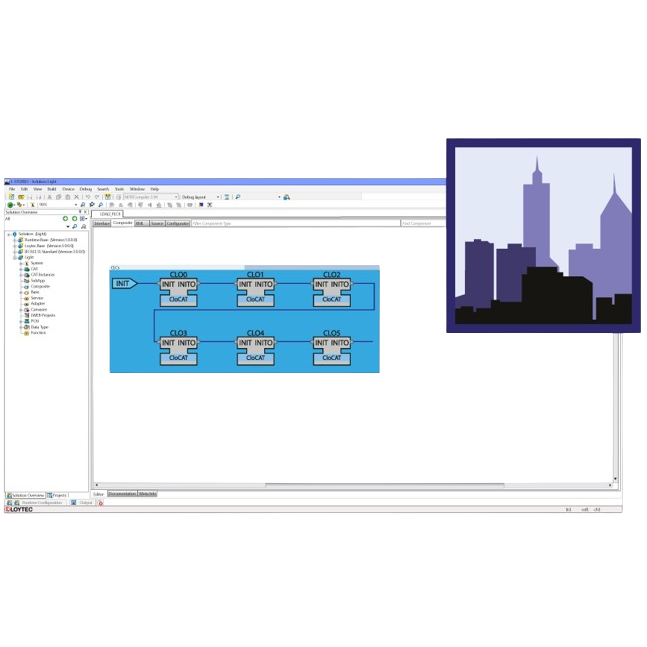
Device configuration and programming suite
LIOB-100
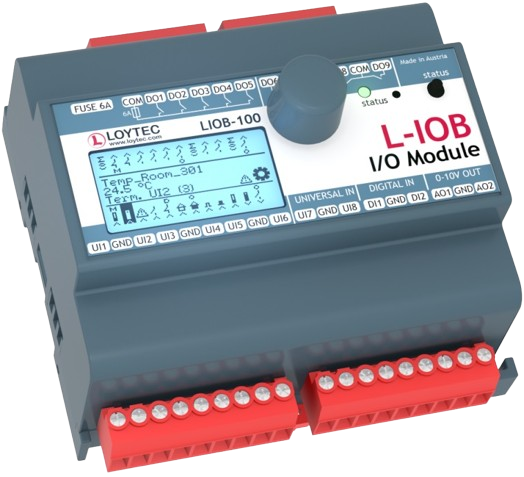
LIOB-Connect I/O Module: 8 UI, 2 DI, 2 AO, 9 DO (5 x Relay 6 A, 4 x Triac 0.5 A)
LIOB-101
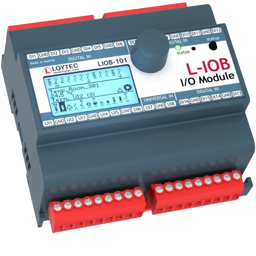
LIOB-Connect I/O Module: 8 UI, 16 DI
LIOB-102
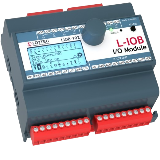
LIOB-Connect I/O Module: 6 UI, 6 AO, 8 DO (8 x Relay 6 A)
LIOB-103
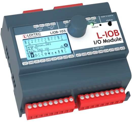
LIOB-Connect I/O Module: 6 UI, 6 AO, 5 DO (5 x Relay 16 A)
LIOB-110
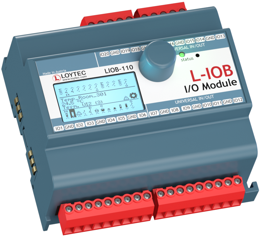
LIOB-Connect I/O Module: 20 Universal I/O (IO)
LIOB-112
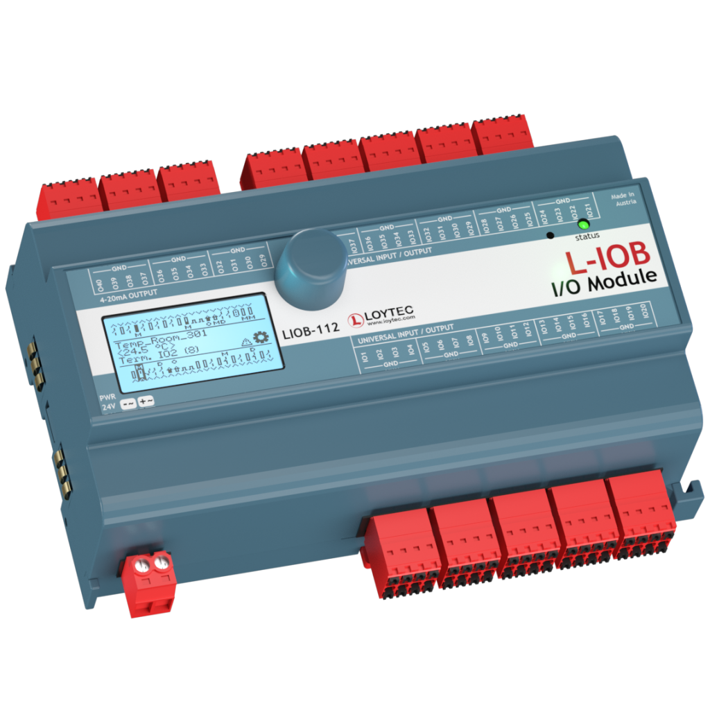
LIOB‑Connect I/O Module: 40 Universal I/O (12 optionally with 4-20 mA Current Output)
LIOB-150
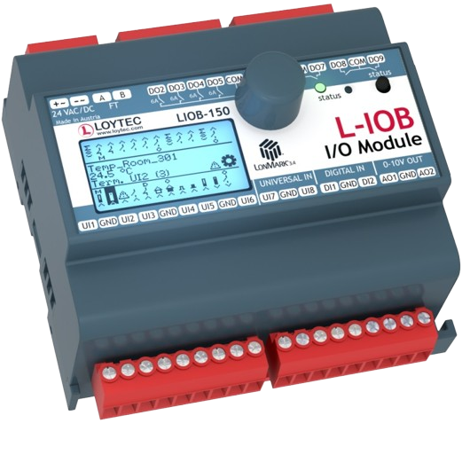
LIOB-FT I/O Module: 8 UI, 2 DI, 2 AO, 8 DO (4 x Relay 6 A, 4 x Triac 0.5 A)
LIOB-151
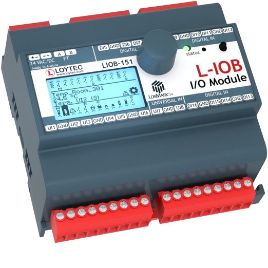
LIOB-FT I/O Module: 8 UI, 12 DI
LIOB-152
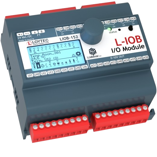
LIOB-FT I/O Module: 6 UI, 6 AO, 8 DO (8 x Relay 6 A)
LIOB-153
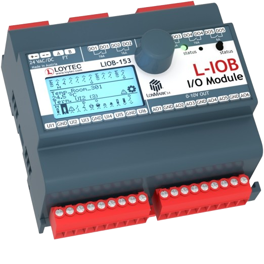
LIOB-FT I/O Module: 6 UI, 6 AO, 5 DO (4 x Relay 16 A, 1 x Relay 6 A)
LIOB-154
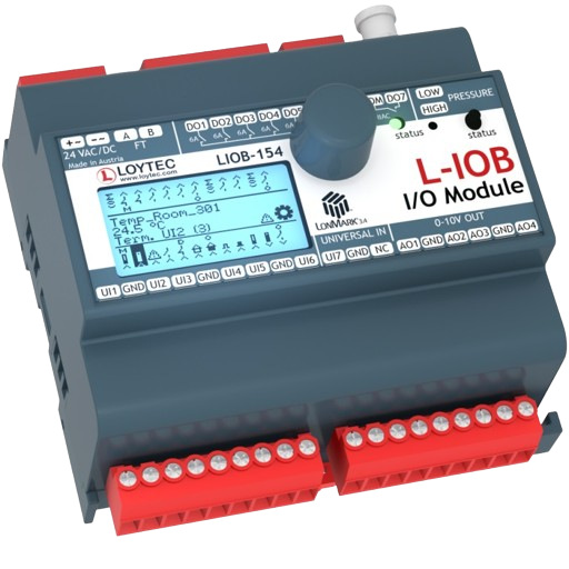
LIOB-FT I/O Module: 7 UI, 4 AO, 7 DO (5 x Relay 6 A, 2 x Triac 0.5 A), 1 Pressure Sensor
LIOB-550
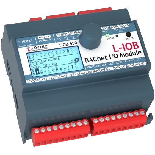
LIOB-BIP I/O Module: 8 UI, 2 DI, 2 AO, 8 DO (4 x Relay 6 A, 4 x Triac 0.5 A)
LIOB-551
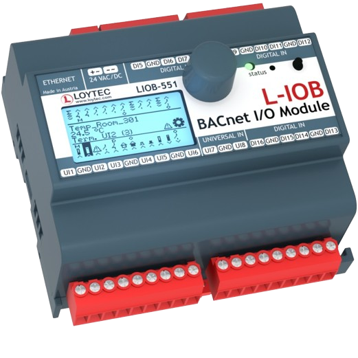
LIOB-BIP I/O Module: 8 UI, 12 DI
LIOB-552
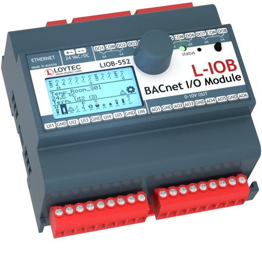
LIOB-BIP I/O Module: 6 UI, 6 AO, 8 DO (8 x Relay 6 A)
LIOB-553
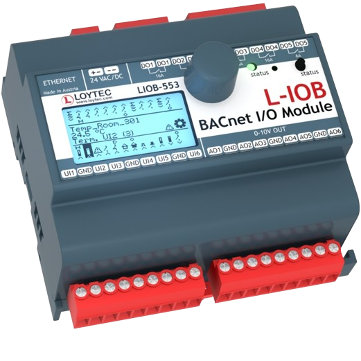
LIOB-BIP I/O Module: 6 UI, 6 AO, 5 DO (4 x Relay 16 A, 1 x Relay 6 A)
LIOB-554
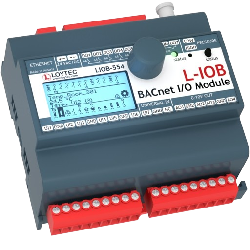
LIOB-BIP I/O Module: 7 UI, 4 AO, 7 DO (5 x Relay 6 A, 2 x Triac 0.5 A), 1 Pressure Sensor
LPOW-2415A
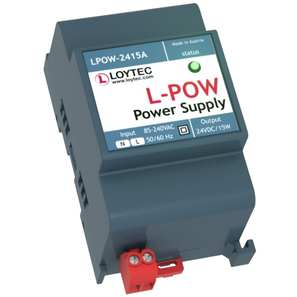
LIOB-Connect Power Supply, 24 VDC, 15 W
LPOW-2415B
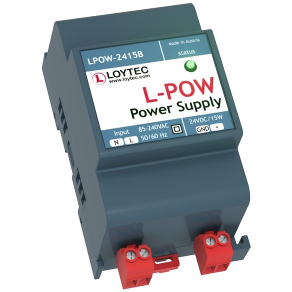
Power supply unit with power connector 24 VDC, 15 W
L-MBUS20
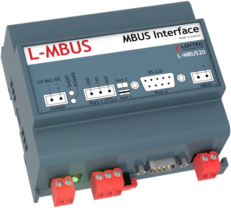
M-Bus level converter, interface for 20 M-Bus devices
L-MBUS80
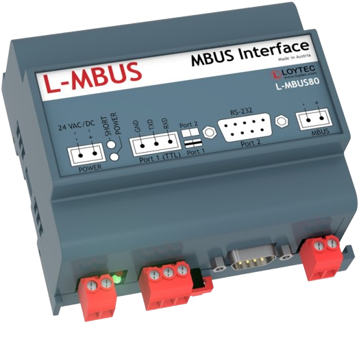
M-Bus Level Converter, Interface for up to 80 M-Bus devices
LKNX-300
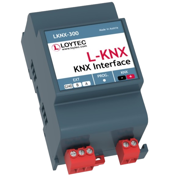
KNX interface to connect KNX TP1 devices
LENO-800
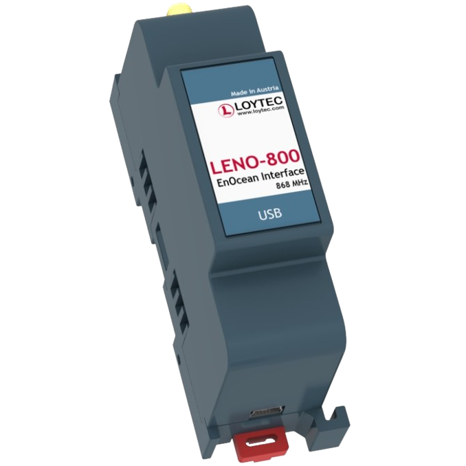
EnOcean Interface 868 MHz Europe
LENO-801
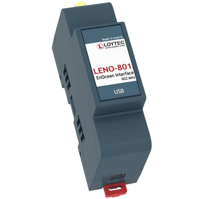
EnOcean Interface 902 MHz USA/Canada
LENO-802
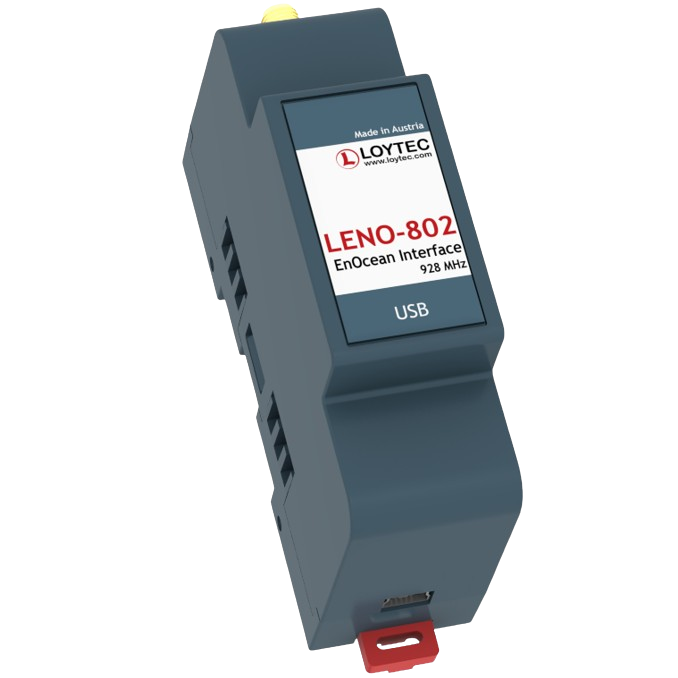
EnOcean Interface 928 MHz Japan
LWLAN-800
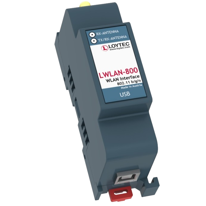
Wireless LAN Interface IEEE 802.11bgn
LMPBUS-804
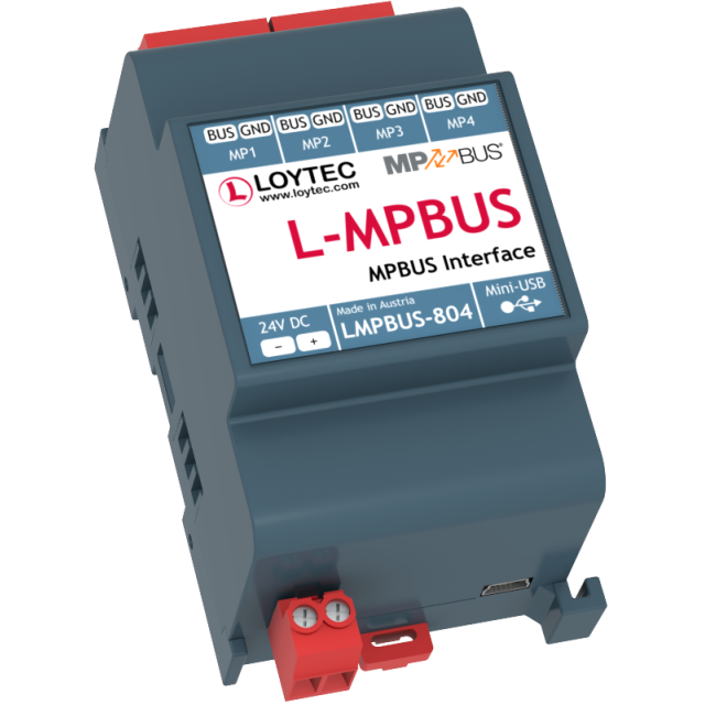
MP-Bus Interface for 16 devices per channel, up to 4 channels
LSMI-800
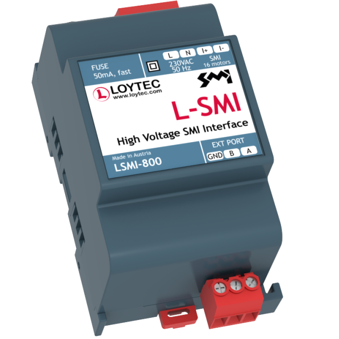
Standard Motor Interface for 16 motors via EXT port
LSMI-804
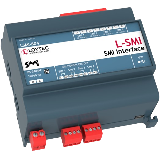
Standard Motor Interface for 64 motors, 4 SMI channels via USB
LRS232-802
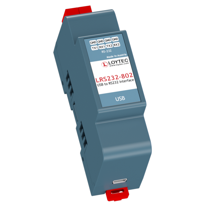
USB to 2x RS-232 Interface

